- Customer group: Guest
-


- Register
- Login
- Your account
- Home
- Details
Products description
Replacing the motor controller board on e.g. the CPC925
Time required: Approx. 45 minutesTools required: 2 mm and 3 mm Allen keys
Step 1: Slightly loosen the worm screw of the alt axis using a 2 mm Allen key. The screw can remain in the handwheel. This screw is only a stop to prevent the handwheel from falling off if it is unscrewed too far. For now, the handwheel should remain up.
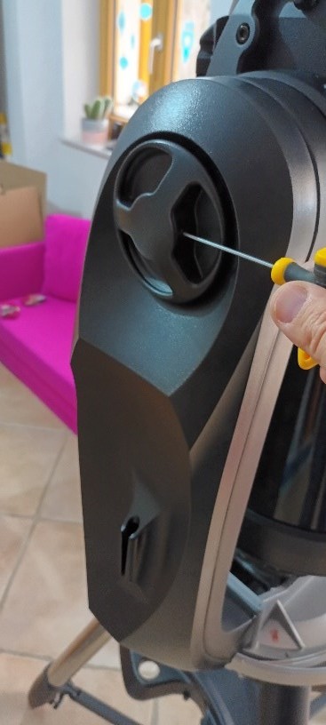
Fig. 1: Unscrewing the worm screw with a 2 mm hexagon socket
Removing the fork cover on the hand controller side. The azimuth axis cover does not need to be removed. There are three different screw lengths.
The bottom four are the same, while the top screw on the hand controller connection side is shorter.
See Fig. 2.
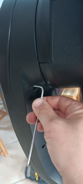
Fig. 2: Unscrew the four lower screws of the cover from the inside (3mm hex key).
The two upper screws are easier to remove with a bent hex key (Fig. 3, 4).
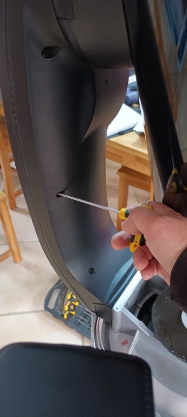
Fig. 3: Unscrew the upper screws. This one is the shorter one.
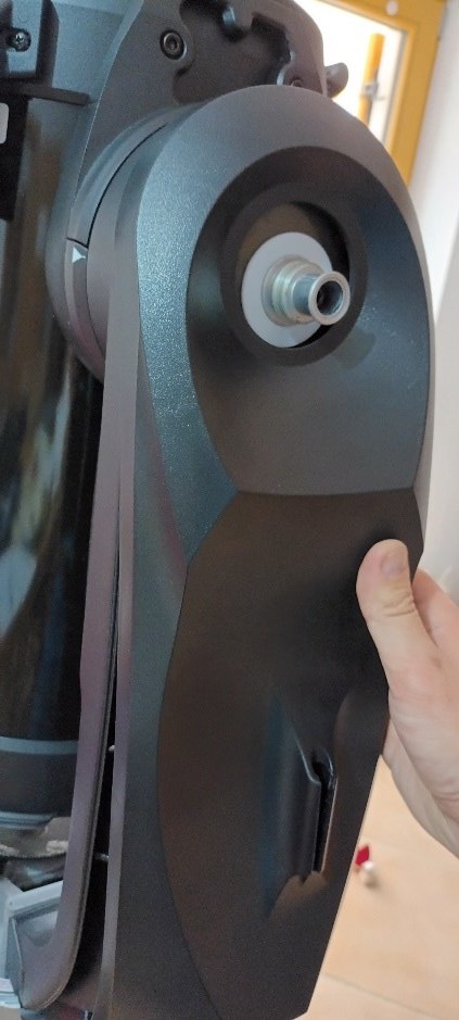
Fig. 4: Unscrew the second longer screw.
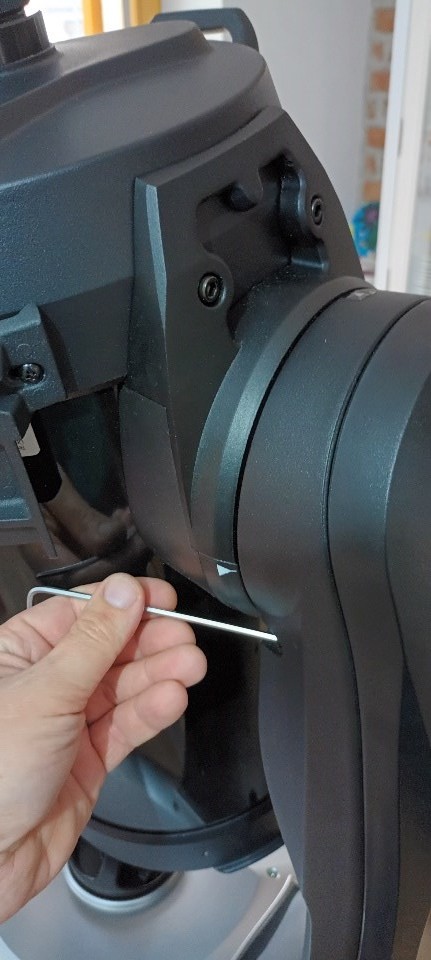
Fig. 5: Unscrew the handwheel and carefully remove the cover.
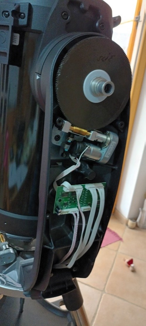
Fig. 6: Exposed monitor controller board. Celestron really did a great job here. All threads are fitted with brass inserts and not cut directly into the plastic like cheap products.
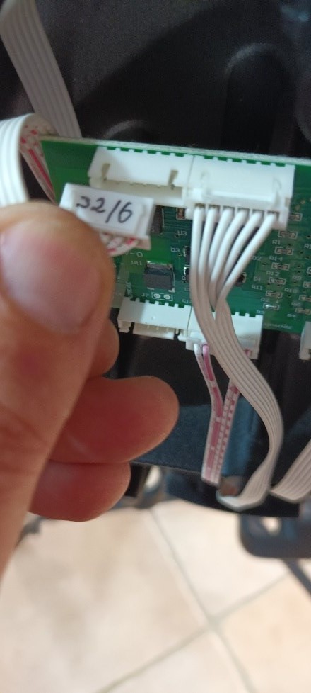
Fig. 7: Unplug and label each connector individually. I did this according to the designation on the circuit board. J2/6 in this case. A mix-up here could potentially have serious consequences.
After all cables have been unplugged, it will look like this (Fig. 8)
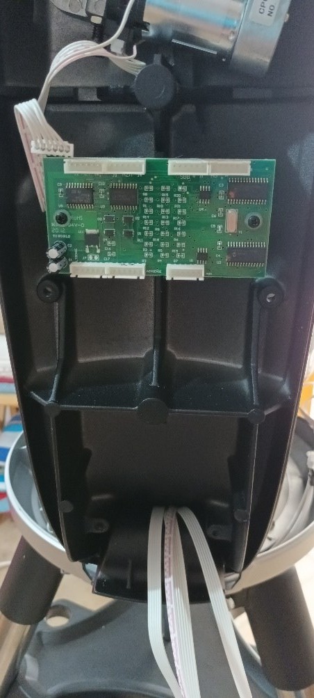
Fig.8: All cables unplugged.
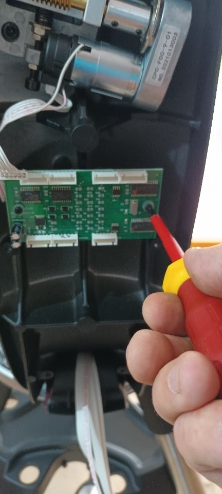
Fig. 9: Remove the retaining screws using a Phillips screwdriver. Caution: There are still plastic washers behind the circuit board. Mark the circuit board with an X or similar symbol to avoid confusing it with the new one.
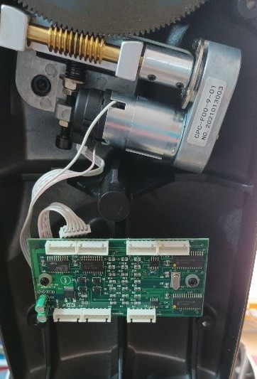
Fig. 10: New motor controller board installed. Easily visible because the capacitors on the bottom left are green compared to the old one (black).
Fig. 11: All cables reconnected. Before reassembling everything mechanically, a quick functional test should be performed. To do this, plug in the hand controller, power up the telescope, and turn it on. Once everything is working, the telescope can be reassembled.
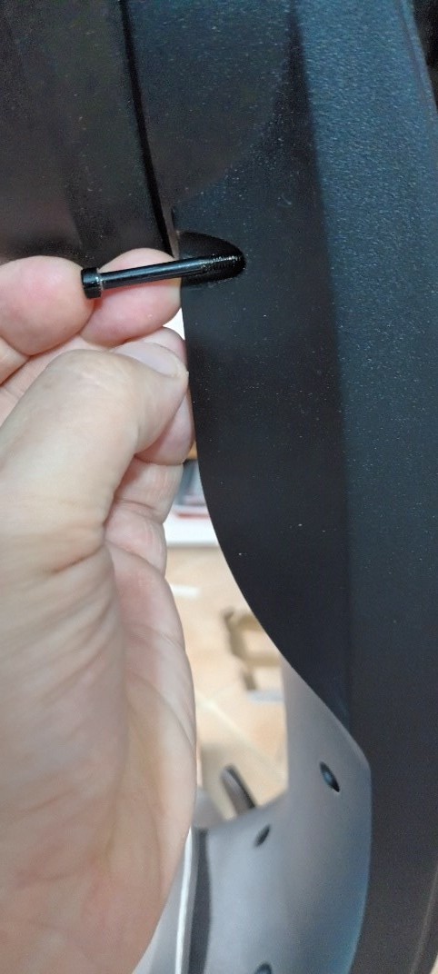
Fig. 12: Replace the cover. Pay attention to the cables inside and screw in the correct screws. The longer of the two long screws goes in here.
The four identical ones go in underneath.
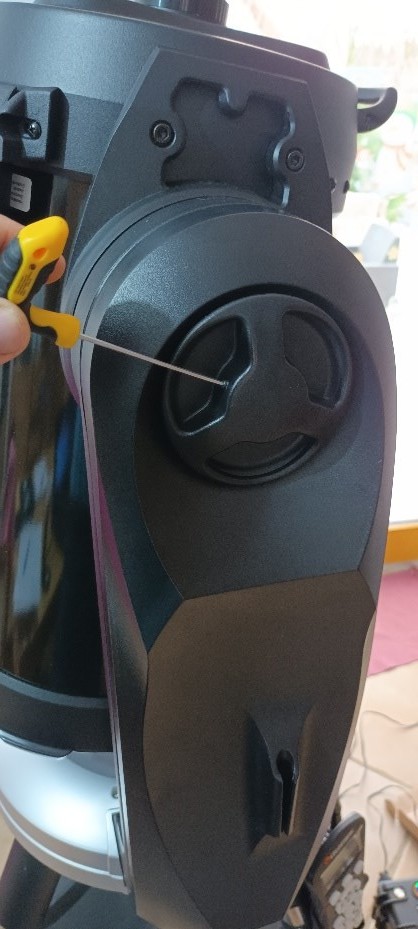
Fig. 13: Screw the handwheel back on and screw in the worm screw just enough so that it no longer protrudes. Done!
Many thanks to Mr. Helfried Passath for these instructions.
This Product was added to our catalogue on 13/03/2023.
Categories
Quick purchase
Welcome back!
Last viewed:

Manufacturer
Shipping country
Payment methods

Die Box kann unter tpl_modified/boxes/box_miscellaneous.html verändert werden. Die Sprachvariablen befinden sich in der Datei tpl_modified/lang/german/lang_german.custom.
Teleskop-Spezialisten © 2026 | Template © 2009-2026 by modified eCommerce Shopsoftware