- Customer group: Guest
-


- Register
- Login
- Your account
- Home
- Details
Products description
Here are the links to jump to the topics:
Theory
The optical components
The setup (here)
The camera: https://www.teleskop-spezialisten.de/shop/Sonnenbeobachtung/Spektroheliographie/Anleitungen-fuer-den-Spektroheliographen-Solex/04-Vergleich-verschiedenerer-Kameras-fuer-das-SolEx::6019.html
The use and software
You've already acquired the optical components, now it's time to assemble them.
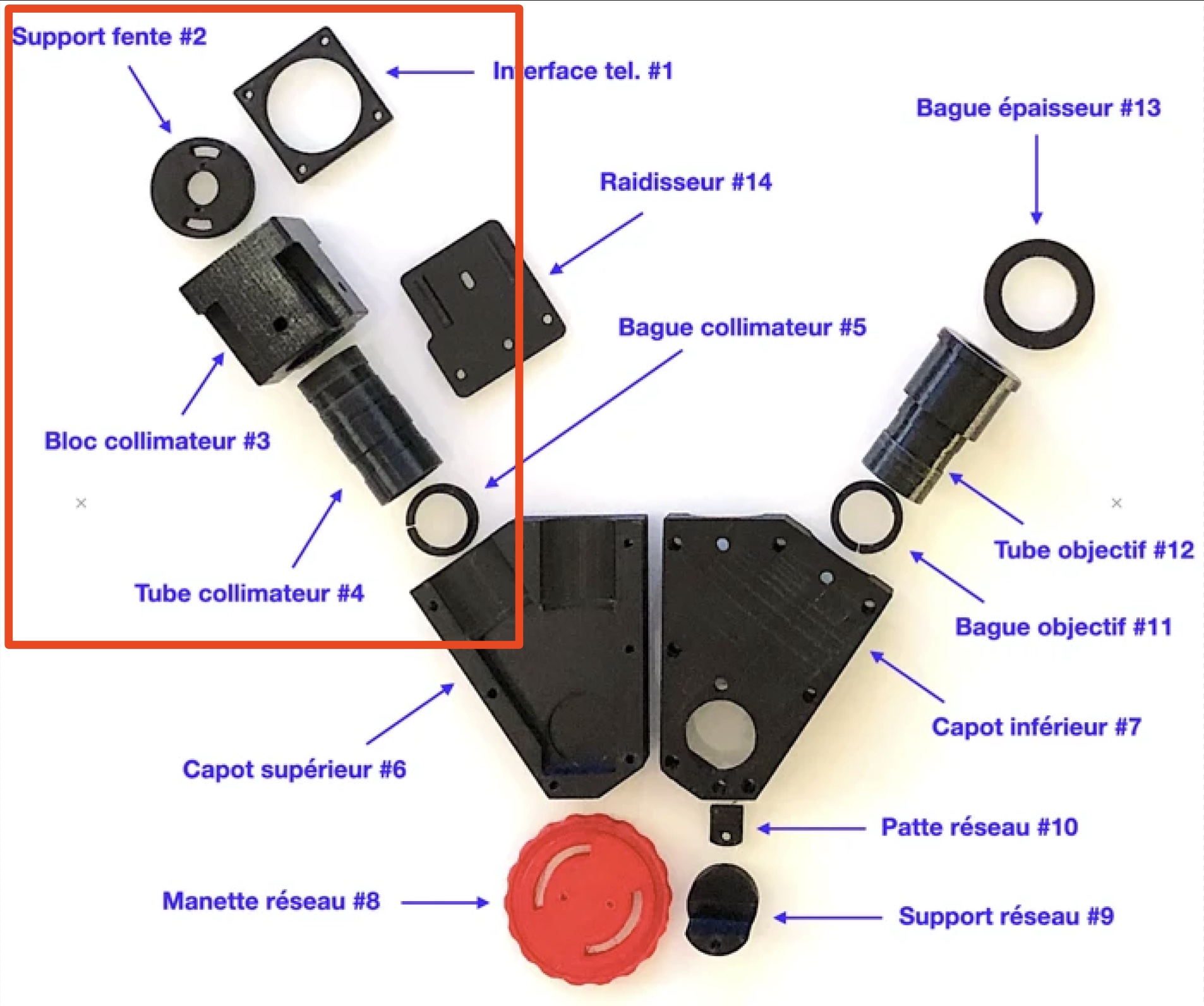
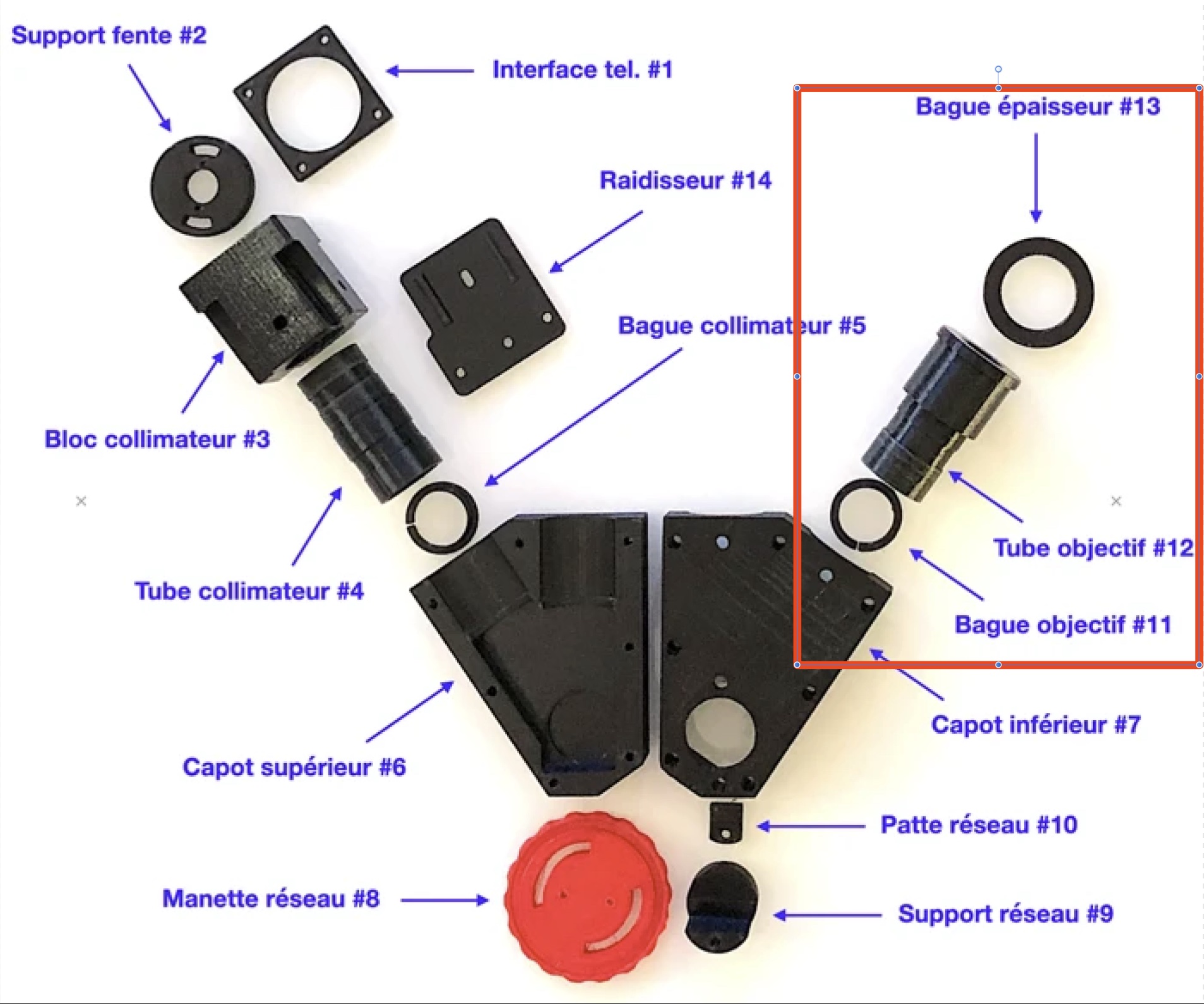
The naming of the components
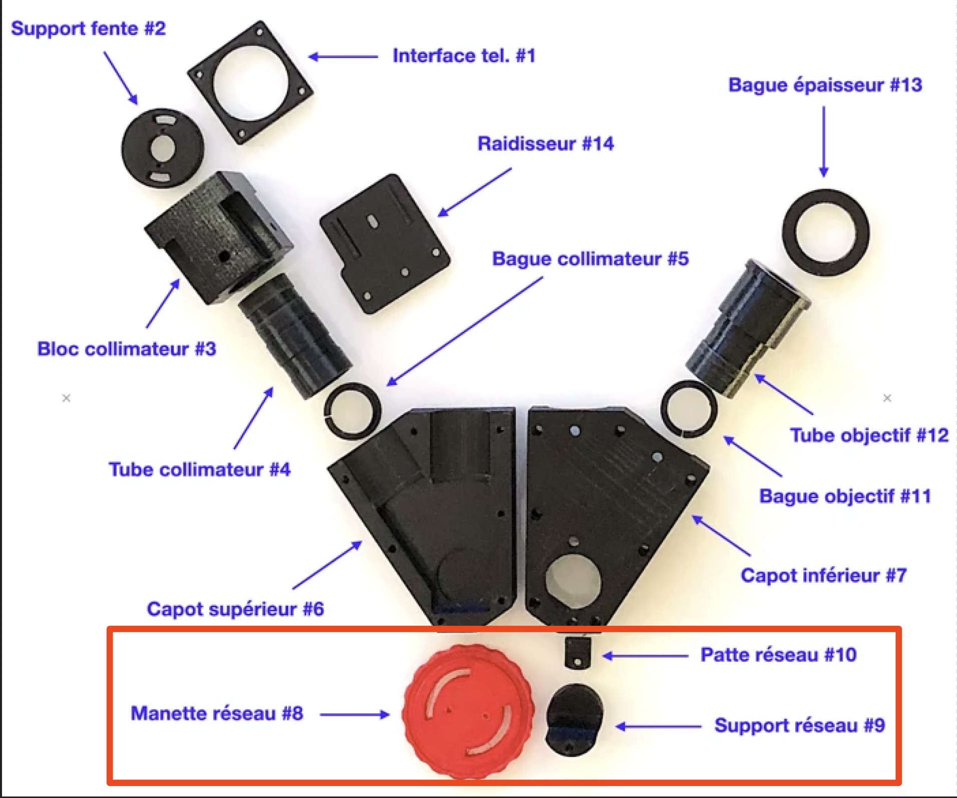
Christian has labeled the components in French. We'll keep this name to make it easier for interested parties to navigate his website and Github.
The following diagram shows all the components of the standard kit:
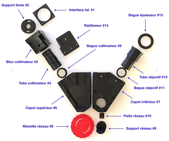
The components already have threaded inserts.
Required Additional Parts
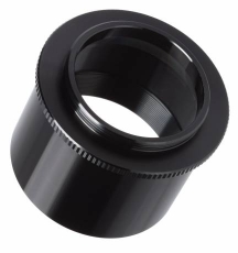
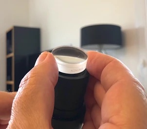
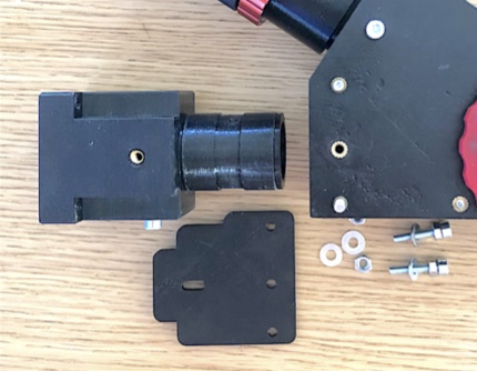
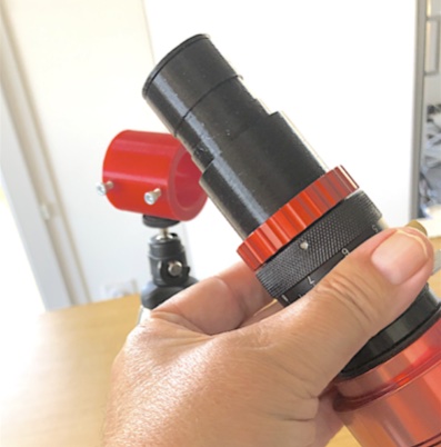
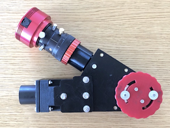
In addition to the 3D-printed kit and the optical elements, using the Sol'Ex is made much easier by adding a precise focusing device for the camera in the form of a helical focuser. There are several options, but note that the Sol'Ex is based on the ZWO model, a photo of which is shown below.
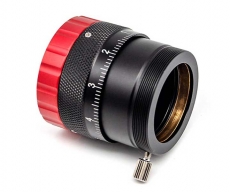
This is available here:
https://www.teleskop-spezialisten.de/shop/Teleskop-Zubehoer/Okularauszug-OAZ/ZWO-1-25-Helical-Auszug-mit-T2-Anschluss-Non-Rotating-System::5976.html
The focusing system is screwed directly onto the end of the "Lens Tube #12" (see nomenclature).
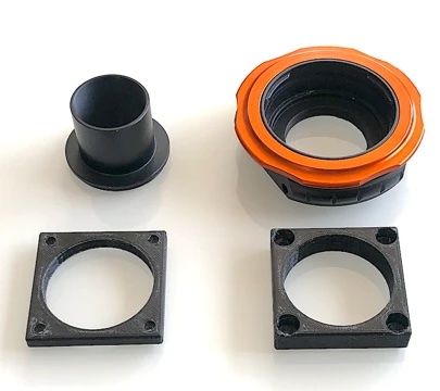
A T2 converter tube (M42 x 0.75 thread) on a 31.75 mm outer slider is required to later attach the spectroheliograph to the telescope's eyepiece holder (most electronic astronomy cameras have this element as an accessory).
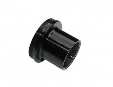
https://www.teleskop-spezialisten.de/shop/Teleskop-Zubehoer/Adapter-u-Verlaengerungen/TS-1-25-Fokaladapter-von-1-25-Steck-auf-T2-Gewinde::4868.html
https://www.teleskop-spezialisten.de/shop/Teleskop-Zubehoer/Adapter-u-Verlaengerungen/Baader-T2-Fokaladapter-fuer-1-25-Steckanschluss-1-25-auf-T2-Gewinde::2796.html
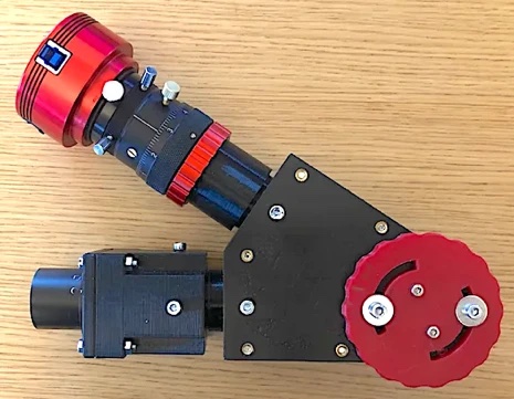
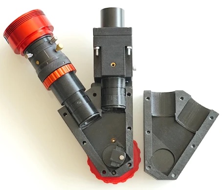
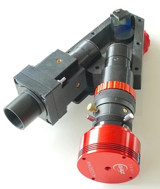
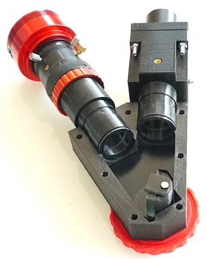
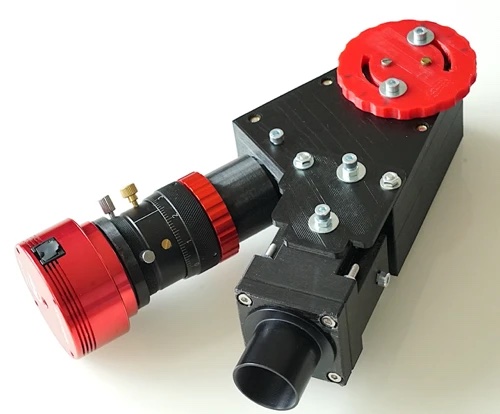
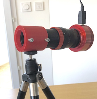
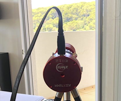
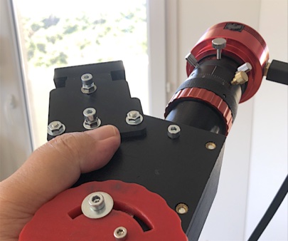
The photo below shows the overall image of the Sol'Ex equipped with the ZWO screw focuser to clearly display the solar spectrum at the detector plane of a CMOS camera (e.g., an ASI178MM or equivalent camera from other manufacturers).
Another important accessory is the camera, which increases the overall price of Sol'Ex. A The selection is relatively wide, but you should opt for cameras with small pixels to achieve high spectral resolution and have more flexibility in configurations (see the "Theory" section). It is strongly recommended to use a monochrome camera for imaging the sun (the Bayer matrix of color cameras reduces the sensitivity and resolution of the solar disk scan too much).
Due to the sensor format and small pixel size, a camera based on the SONY IMX178 sensor is ideal for Sol'Ex, such as the ASI178MM from ZWO or the ToupTek G3M178M (the latter very practical due to the small size of the housing).
ToupTek G3M178M
https://www.teleskop-spezialisten.de/shop/Astrofotografie/ToupTek-Photonics/ToupTek-G3M178M-IMX178-USB3-0-ungüehlte-kompakte-CMOS-Kamera-178-Mono-mm::5563.html
ZWO ASI178MM
https://www.teleskop-spezialisten.de/shop/Astrofotografie/ZWO-ASI178MM-SW-CMOS-Astrokamera-USB3-0-Sensor-D-8-82mm::3926.html
Click here for a comparison of various cameras for the Sol'Ex: [Link]
Connecting to the Telescope / Lens
Two categories of observation instruments are possible: an astronomical telescope, and a photographic telephoto lens. Both are suitable for taking solar images with the Sol'Ex.
We do not recommend using a reflecting telescope because it is too large, too bright, too dangerous for the equipment, and does not improve image quality. However, we have successfully used Newtonians with anti-reflective primary mirrors.
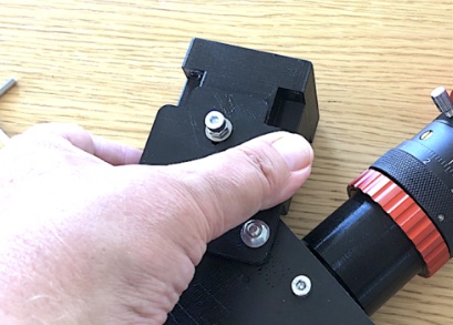
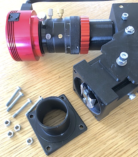
To connect the Sol'Ex to a telescope, the best and easiest method is to use a 31.75 mm (1.25") adapter. All you need is a T2 to 31.75 mm adapter in your accessories, which you screw onto "Telescope Interface #1" (see nomenclature). A "2-inch" interface for a 50 mm slider can also be adapted to the Sol'Ex via the T2 thread and is advantageous if your eyepiece holder allows this diameter due to the increased rigidity.
T2 thread to 2" thread adapter
https://www.teleskop-spezialisten.de/shop/Teleskop-Zubehoer/Adapter-u-Verlaengerungen/EXPLORE-SCIENTIFIC-Adapter-2-auf-T2::4860.html
To mount Sol'Ex behind a telephoto lens, you need a T2 interface ring for the bayonet mount model (Canon, Nikon, etc.). GEOPTIK, for example, offers this type of adapter.
The photo below shows these two types of adapters, one for a telescope and one for a photographic telephoto lens, screwed onto the "Telescope Interface #1" part.
Tools required:
a screwdriver,
a set of Allen keys,
a 7 mm open-end wrench,
cotton wool for cleaning a dirty lens surface (be careful, the surface of a diffraction grating cannot be cleaned; you can't rub it off, even very carefully).
If you are printing the components yourself, you will also need the following parts:
Many Sol'Ex parts require M3 and M4 threads. In most cases, we prefer to use inserts specifically designed for 3D-printed parts rather than cutting threads directly into the material, which is too fragile.
For Sol'Ex, you will need inserts for M3 and M4 screws. These inserts are hot-mounted, as you will see below. We use RUTHEX models, see these links:
- RUTHEX M3 model
- RUTHEX M4 model
An M3 tap,
An M4 tap,
Two 3 mm and 4 mm drill bits for deburring the holes,
A medium-strength sandpaper, which is essential for deburring 3D-printed parts,
M3 and M4 screws.
And now let's get started...
Assembling Sol'Ex
Printing all the parts that make up Sol'Ex takes between 1 and 2 days if you do it yourself (remember: you can easily order the entire mechanical kit from us). Assembly and adjustment take a maximum of half a day, after which you can observe the whole process.
The following parts of this page show step by step how to assemble and adjust Sol'Ex. We're happy to answer any questions you may have.
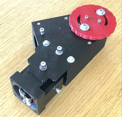
Here are some views of Sol'Ex during the construction phase to give you an initial overview:
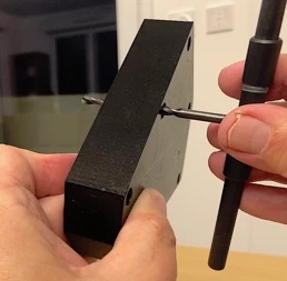
Inserting the Threaded Inserts (only for self-printing; they are already inserted in the kit)
This section shows, with a few pictures, how to install inserts into a 3D-printed part.
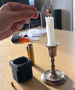
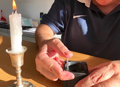
Christian uses the candle technique to heat the inserts. There are other methods, such as using the hot tip of a soldering iron. "But the candle is so much more romantic... (Christian's exact words)."
Screw the insert into the end of a long screw to avoid burning your fingers. Heat the insert in the candle flame for 8 to 10 seconds. It will turn black, but that's okay. Insert the burning insert into the hole in the PETG piece. Push it in far enough so that it is the correct depth and does not touch the insert. Wait a few moments while the screw is vertical, then unscrew it. The insert is now welded into the PETG structure and is one with it. It can no longer be removed; that's the purpose of the procedure.
Please note that there is a specific direction for the insert to be inserted into its hole: the narrowest and smoothest part must be inserted first.
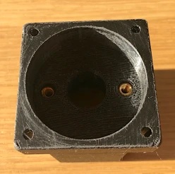
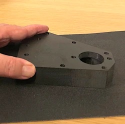
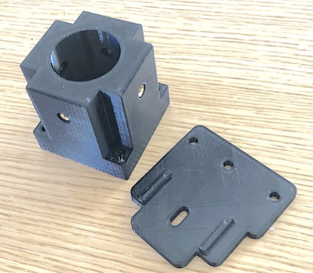
Assembling the Case
We continue with the assembly of the two parts of the Sol'Ex case, the "top cover #6" and "bottom cover #7" parts (see the nomenclature in Part 2).
For self-printing (already done in the kit):
Start by deburring the holes with an M4 drill bit and sanding the parts that lie between the two case parts:
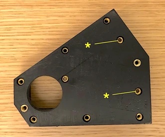
There are several M4 inserts that need to be inserted into the bottom cover. All of them need to be pushed in generously, except for the inserts marked with "*" in the adjacent illustration. Make sure these two do not protrude beyond the opposite side, which forms a half-cylinder. Calculate your depth carefully when inserting these two inserts.
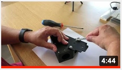
The rest of the case assembly, including the "Stiffener #6" part, is explained in a video. Click on the image to watch it.
Assembling the grille holder
Now it's time to assemble the grille into its holder and into the housing. The sensitivity of the grille requires careful and thoughtful handling.
To be clear: A fingerprint on the engraved surface of the grille means it's going straight into the trash. There's no way it can be salvaged from an accident; it's irreversible. There's no way to make a mistake. The only way to handle a grille is to hold it by the sides and let it rest on the side opposite the engraving (the engraved side is easy to identify; it creates the colored iridescence on the surface). Very thin gloves can be worn, but touching the surface with such gloves will still damage the surface!
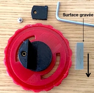
Installation direction of the diffraction grating.
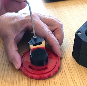
Installing the grating holder.
Assembling the collimator cube, collimator tube, and slit
This section shows how to print the "Collimator Block No. 3" element, how to attach the inserts, how to insert the collimator lens (125 mm focal length) into the collimator tube No. 4, and finally how to install the Sol'Ex entrance slit.
Inserting the optics into the collimator tube.
View of the collimator optics used from above.
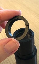
Inserting the retaining ring.
"Collimator Block" and "Stiffener #14." The latter facilitates adjusting and holding the collimator block.
252 / 5.000
Collimator tube #4, with its 80 mm focal length lens, is slid into collimator block #3. On the opposite side of the block, mount slot holder #2 with the slot and the 10-micron slit attached to it.
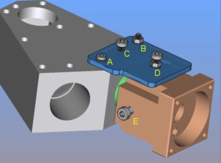
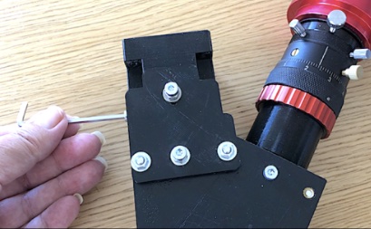
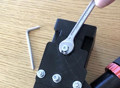
The collimator tube is pushed into the opening in the housing until it touches the back. Then, stiffener #14 is installed. This is done using the two screws A and B from the Sol'Ex housing.
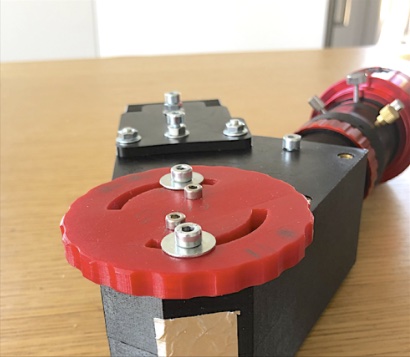
In D is a screw, nut, and washer assembly that passes through a slotted hole. This hole allows the collimator block to be moved in translation. Here's how to tighten it:
1 - Insert screw C and tighten it slightly to secure the tube in the collimator.
2 - Tighten nut C, which firmly secures the stiffener to the housing.
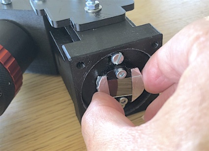
Thanks to the slotted hole in screw D, you can freely slide the collimator block up to a few millimeters along the collimator tube (screw E is not tightened, or its equivalent on the opposite side):
It is important to align the slot correctly: In this illustration, the 4.5 mm slot's longitudinal axis is perpendicular to the table plane.
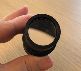
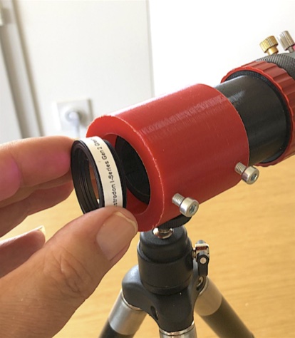
Assembling the Lens
The 125 mm focal length camera lens is now installed in the 12" lens barrel and coupled to the recording camera.
Video: pBILZ7zOx9Q
Adjusting the Camera Lens
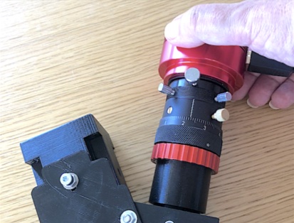
To get a sharp image in the Sol'ex, the camera must be focused to infinity.
In the next step, the focus of the unit, which consists of the 125 mm lens barrel, the lens itself and a camera, is set to infinity.
The whole thing consists of a small telescope connected to an electronic camera (here an ASI178MM). The device is attached to a photographic tripod, for example. The goal is to obtain a sharp electronic image of a landscape several kilometers away.
Optional: The contrast of the image and thus the accuracy of the adjustment is best if you place a bandpass filter in front of the lens, which isolates the green part of the spectrum.
You aim through an open window at a distant landscape.
.jpg)
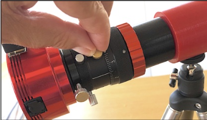
The focus ring of the helicoidal focuser is used to make the image as sharp as possible.
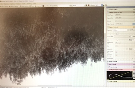
To do this, use your preferred capture software, SharpCap in this case. It's extremely important that the focus is in the center of the field. If the focus is in the center, it's normal for the image to be quite blurry in the corners.
Fix the focus with the focusing screw. This is a reference position that you should maintain.
Pasted Graphic 30.png
Push the lens barrel into the mount of the Sol'Ex housing. Push it all the way in and secure the lens with the clamping screw. Tighten the lens firmly onto the housing (moderately!).
Adjusting the Collimator Lens
The goal is to ensure that the light rays emerging from a point on the slit after the collimator lens (toward the diffraction grating) are as parallel to each other as possible. If this adjustment is not performed properly, the quality of the images of the Sun will suffer (especially the appearance of optical astigmatism). We will use the (previously adjusted) camera lens as the working tool here. See the adjacent video.
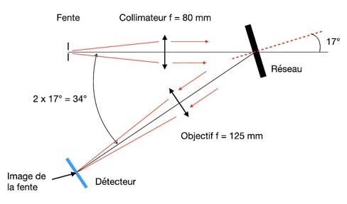
The procedure is based on observing the image of the slit with the camera at the "zero order" of the grating. In other words, the grating is used as a common mirror. To achieve this, in the Sol'Ex configuration, the angle of the light rays arriving from the collimator must be exactly 17° on the grating. This angle is achieved when the image of the non-dispersed slit appears on the detector as a thin line. Rotate the grating wheel to find this zero-order image of the slit. The following diagram will then be reproduced:
The lens end of the Sol'ex is pointed at a white wall, and images are captured with the camera. The goal is to find the zero-order image from the slit.
The zero-order image is an image not scattered by the grating, which is directed to the sensor when the grating is used like a simple mirror. To achieve this, the angle of incidence on the grating must match the angle of reflection, which directs the light rays to the center of the sensor. In Sol'Ex, the angle is 17".
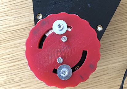
Turn the lever to achieve the configuration shown above.
Pasted Graphic 37.png
At the same time, watch your recording screen. You'll see that the slit appears at a specific moment. It's important that it's centered vertically and horizontally with respect to the sensor surface.
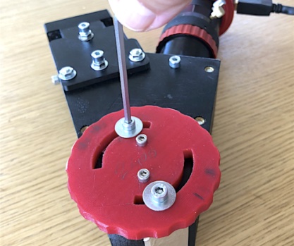
To center the image of the slit horizontally, you can tighten the screws on the power lever with a certain amount of force. You'll probably also perform this procedure on the telescope itself when observing the Sun.
Initially, the image from the slit will likely be blurry. Move the collimator block to achieve the sharpest possible image, especially in the center of the image.
Tighten the two screws at a 90° angle to the block, ensuring the image of the slot remains sharp. Start slowly and distribute the force evenly across the two screws.
Tighten the nut on the side of the collimator block.
The image of Order 0 will be horizontal on the screen. To do this, slightly loosen the two M4 screws that secure the slotted disc. Turn it and watch what happens on the screen. With a little patience, you'll get it. Avoid touching the slot with your fingers (it can be cleaned with water and cotton wool, though; don't panic).
Pasted Graphic 45.png
Tighten the two M4 screws moderately.
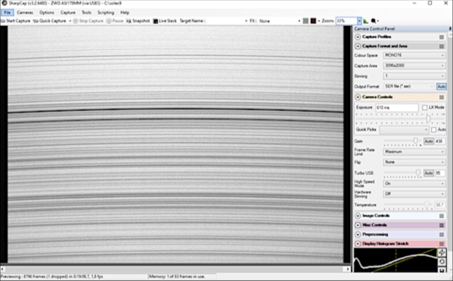
Aim at the daytime sky background and adjust the array lever to roughly center on the sodium doublet region, which is quite rich in lines.
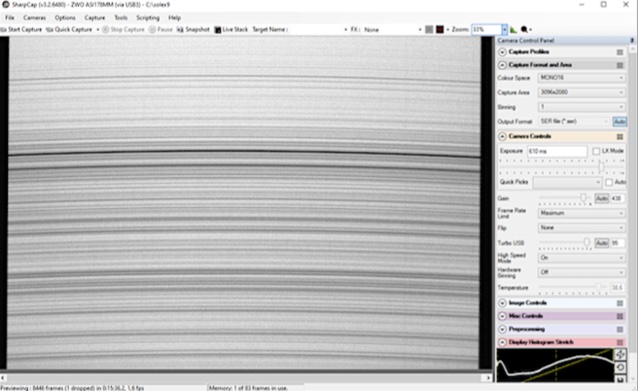
At this stage, the solar spectrum may be slightly blurred. This is normal and due to the optical properties of Sol Ex. Feel free to adjust the focus using the helical focusing system. The adjustment should be on the order of 1/10 mm. You may also notice that the left and right edges of the spectrum trace are not perfectly vertical, as in this photograph above (slightly so).
To vertically position the dispersion axis (which is highly recommended), slightly loosen the screws holding the 31.75 mm camera head and gently rotate the camera to obtain the result while observing the computer screen. Then retighten the screws.
Your spectral lines are horizontal (except for the smile curve) and sharp, the dispersion axis is vertical... the adjustment of your Sol'Ex spectrograph is complete! Depending on the spectral range you're targeting, you may need to adjust the helical focus (especially in the blue range), but this is routine and easily remedied by checking the sharpness of the lines. You no longer need to touch the collimator or the slit alignment. These adjustments are stable and will last a lifetime!
Now all you have to do is attach the telescope interface to the 31.75 mm or 50 mm glider using 4 M4 screws via the interface part #1.
ou can now use Sol'Ex to observe the daytime sun.
————
Graphics and images were taken from Christian Buil, who developed Sol'Ex.
This Product was added to our catalogue on 18/11/2022.
")

Die Box kann unter tpl_modified/boxes/box_miscellaneous.html verändert werden. Die Sprachvariablen befinden sich in der Datei tpl_modified/lang/german/lang_german.custom.