- Kundengruppe: Gast
-


- Registrieren
- Anmelden
- Mein Konto
- Startseite
- Details
Produktbeschreibung
Theorie von Sol’Ex (SolEx)
Ein wenig Instrumententheorie... Diejenigen, die der Mathematik eher abgeneigt sind, können diesen Teil überspringen, das sollaber nicht davon abhalten, Sol'Ex zu bauen und zu benutzen! Für alle anderen finden Sie hier eine Begründung für die Konstruktion dieses Instruments, seine Größe und den Ursprung seiner Leistung.
Wenn Sol'EX ein Spektroheliograph ist, ist es in erster Linie ein Spektrograph, d. h. ein Instrument, das die Zerlegung von Lichtstrahlung in Wellenlängen oder Farben, wenn man so will, aufzeichnet. Christian hat für Sol Ex die klassischste und einfachste optische Anordnung gewählt, die es gibt, wie hier gezeigt wird.
Die folgende Abbildung zeigt das optische Schema:
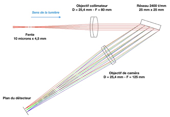
Das Instrument besteht aus einem schmalen, 10 Mikrometer breiten und 4,5 mm hohen Eintrittsschlitz, der im Brennpunkt des Beobachtungsfernrohrs angeordnet wird. Dann folgt ein Kollimatorobjektiv mit einer Brennweite von 80 mm, das aus zwei verklebten Linsen besteht. Dieses achromatische Dublett wurde speziell für Sol Ex optimiert und verwendet ein spezielles Glas mit hohem Index. Dieses Objektiv lässt die Lichtstrahlen, die von einem Punkt des Schlitzes ausgehen, parallel zueinander verlaufen. Die Lichtstrahlen treffen dann auf ein holographisches Beugungsgitter mit 2400 Strichen/mm, das das Licht spektral streut. Ein ebenfalls speziell für Sol Ex hergestelltes Objektiv mit einer Brennweite von 125 mm fokussiert schließlich alle Strahlen in der Detektorebene.
Die durchschnittliche Richtung der Strahlen vor und nach dem Gitter bildet ein "V" mit einem Innenwinkel von 34°. Dieser Winkel wird als "Gesamtwinkel" bezeichnet. Er verleiht dem Sol Ex seine charakteristische Gesamtform.
Es fällt sofort auf, dass die Strahlen aus dem Kollimator in einem sehr steilen Winkel auf das Gitter auftreffen, etwa 72°, wenn man um die H-Alpha-Wasserstofflinie bei 656 nm Wellenlänge arbeitet. Dieser starke Einfall führt zu einer starken Vignettierung der vom Fernrohr gesammelten Strahlen, wobei das Gitter mit seiner Grenzgröße ungefähr die Pupille des Systems darstellt. In der Streuebene (wie in der Abbildung dargestellt) beträgt die Öffnung des angenommenen Strahls etwa f/10,6. In der senkrechten Ebene und unter Berücksichtigung des durch den 4,5 mm hohen Schlitz abgedeckten Bereichs beträgt die Blende des Systems etwa f/5,6. Welche Bedeutung hat dies alles? Angenommen, Sie verwenden ein Fernrohr mit einem Durchmesser von 65 mm und einer Brennweite von 420 mm. Das Öffnungsverhältnis dieses Fernrohrs beträgt dann etwa 420 / 65 = 6,5. In der ersten Ordnung, wenn das Fernrohr mit Sol'Ex verwendet wird, beträgt die effektive Öffnung also f/6,5 entlang der Achse senkrecht zur Einfallsebene (die physikalische Öffnung des Fernrohrs ist die Grenze) und f/10,5 in der Einfallsebene (Sol'Ex ist die Grenze). Wenn man die tatsächliche Kontur der Nutzfläche am Objektiveingang zeichnen könnte, hätte man die Form einer Ellipse und nicht eines Kreises.
Die Dimensionierung von Sol'Ex führt also zu einem Verlust des Lichtstroms, da Ihr Fernrohrobjektiv abgeblendet wird (außer Sie verwenden ein Fernrohr, das nativ auf etwa f/10 geöffnet ist). Diese Situation ist bei der Sonnenbeobachtung nicht kritisch, da der verfügbare Lichtstrom wirklich reichlich vorhanden ist. Fotografische Optiken und Objektive, die mit Sol'Ex verwendet werden können, können zwischen f/5,6 und f/9 geöffnet werden, ohne dass dies einen sichtbaren Effekt auf die Bilder hat. Trotzdem können Sie, wenn Ihr Instrument von Grund auf sehr offen ist, vor dem Objektiv verschiedene Blenden ausprobieren, um es zu schließen und so eine mögliche Verbesserung der Bildqualität zu testen. Ich führe im Abschnitt "Beobachtung" einige Beispiele an. Führen Sie verschiedene Versuche durch. Dies verhindert auch, dass Sie einen übermäßigen Lichtfluss unnötig auf einen kleinen Punkt am Eingang von Sol Ex konzentrieren. Wenn Sie beispielsweise ein Fotoobjektiv mit einer Blende von f/2,8 verwenden wollen, sollten Sie die Blende auf f/5,6 oder sogar f/7,5 einstellen (die Beugung verschlechtert die Leistung im Allgemeinen noch nicht im Hinblick auf die Eigenschaften von Sol'Ex).
Der starke Einfall auf das Gitter verursacht zwar einen Flussverlust, erweist sich aber im Hinblick auf die Auflösung des aufgenommenen Spektrums als sehr vorteilhaft. Um diesen letzten Punkt zu verstehen, muss man den großen Unterschied in der Größe des Lichtstrahls in der Einfallsebene vor und hinter dem Gitter (D1 bzw. D2) beachten:
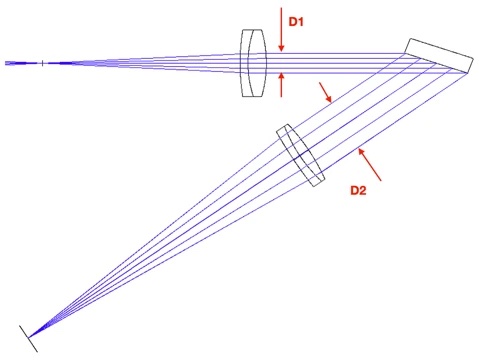
Diese Eigenschaft, die für die Verwendung eines Gitters typisch ist, wird Anamorphose genannt.
Neben der Größe der Strahlenbündel wirkt sich die Anamorphose auch auf die Größe des Bildes des Schlitzes auf dem Detektor aus. Das Bild der Schlitzbreite wird um einen Faktor D1/D2, den sogenannten Anamorphosefaktor, verkleinert. Die Größe ist dagegen entlang der sogenannten Raumachse, die senkrecht zur Dispersionsachse verläuft, unverändert. Zur Veranschaulichung zeigt das folgende Dokument das Bild eines Lichtwellenleiters, der vorübergehend den Schlitz des Sol Ex ersetzt, mit einer anfangs runden Kontur, deren Bild am Ende jedoch oval ist:
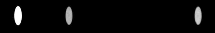
Abb.: Aussehen einiger monochromatischer Bilder einer am Eingang von Sol Ex angeordneten Glasfaser für Wellenlängen in der Nähe der H-alpha-Linie.
Die durch die Anamorphose verursachte Verringerung der optischen Breite des Schlitzes hat einen deutlichen Einfluss auf das spektrale Auflösungsvermögen von Sol'Ex, d. h. auf die Feinheit der beobachtbaren Details des Spektrums. Im Fall von Sol'Ex ist dieser Einfluss sehr positiv. Er ist verantwortlich für die hohe Leistung, die erreicht wird, obwohl Sol'Ex ein kompaktes Instrument ist.
Lassen Sie uns ein paar Berechnungen anstellen. Zunächst eine praktische Formel, die den Gesamtwinkel G (in Sol'Ex G = 34°) und den Einfallswinkel alpha auf dem Gitter miteinander verbindet:
alpha = arcsin(k m lambda0 / (2 cos G/2) + G/2.
Mit k, der Beugungsordnung (hier k = 1), m, der Ätzdichte (hier m = 2400 Striche/mm) und lambda0, der Wellenlänge in der Mitte des Sensors (hier 0,6563x10⁻³ mm). Außerdem ist G = alpha + beta, wobei beta der Beugungswinkel ist.
Bei der Beobachtung der H-alpha-Linie (6563 A) ist der Einfallswinkel der Strahlen auf das Gitter genau alpha = 72,4°, während der Beugungswinkel (nach dem Gitter) beta = 38,4° ist. Der Anamorphosefaktor wird durch die Formel :
A = A = cos(alpha) / cos(beta).
woraus sich ergibt, dass A = cos(72,4°) / cos(38,4°) = 0,386. Das bedeutet, dass die Breite des Eingabeschlitzes gewissermaßen reduziert wird. (optisch ) auf 0,386 x 10 Mikrometer = 3,86 Mikrometer. Es ist dieses Ergebnis, das einen Gewinn an spektraler Auflösung bewirkt. Es muss hinzugefügt werden, dass bei der roten Wasserstofflinie, aber auch bei einem großen Teil des sichtbaren Spektrums, die Optik von Sol Ex durch Beugung quasi begrenzt ist, d. h. sie ist sehr gut (sobald man nicht gleichzeitig einen sehr großen Spektralbereich erforscht).
Das Auflösungsvermögen R ist durch die Formel R = λ / Δλ definiert, wobei λ die Beobachtungswellenlänge und Δλ das feinste beobachtete Detail im Spektrum in Wellenlängeneinheit ist. Wir stellen fest, dass R eine dimensionslose Zahl ist. Je größer R ist, desto mehr feine Details werden im Spektrum beobachtet. Wir zeigen, dass :
R = fc / w x (tan(alpha) + sin(beta) / cos(alpha))
Dabei stehen alpha und beta für den Einfalls- bzw. Beugungswinkel auf das Gitter. Außerdem ist fc die Brennweite des Kollimators, hier fc = 80 mm, und w die physikalische Breite des Schlitzes, hier w = 10 Mikron = 0,010 mm. Das Phänomen der Anamorphose wird durch den Term in Klammern in dieser Formel beschrieben, ebenso wie die Auswirkung der Ätzdichte des Gitters. Wenn man die Berechnung um die H-alpha-Linie herum durchführt, findet man :
R = 80 / 0,010 x (tan(72,4°) + sin(38,4°) / cos(72,4)) = 41600.
Unter Berücksichtigung der verbleibenden optischen Aberrationen kann man davon ausgehen, dass das Auflösungsvermögen von Sol'Ex nahe bei R=40000 liegt, was für ein so kleines Instrument eine bemerkenswerte Leistung ist. Man löst also theoretisch im Roten (aber über eine kleine Breite in der Wellenlänge) spektrale Details von Δλ = λ / R = 6563 / 40000 = 0,16 A = 0,016 nm auf. Aufgrund dieser Feinheit ist die Reinheit der von Sol'Ex gelieferten monochromatischen Bilder besser als die, die mit den viel teureren Interferenzfiltern erreicht wird.
Erinnern wir uns an die grundlegende Formel für Gitter, die den Beugungswinkel mit dem Einfallswinkel verknüpft:
sin(alpha) + sin(beta) = m x λ.
Mit m die Ätzdichte, hier m = 2400 Striche/mm und λ die Wellenlänge, hier λ = 0,6563e-3 mm. Sie können kontrollieren, ob die Werte für Alpha und Beta korrekt sind.
Ein weiterer wichtiger optischer Parameter ist der spektrale Dispersionsfaktor in der Ebene des Detektors. Dabei geht es um die Bewertung des kleinen Spektralbereichs, der von einem Pixel des Detektors abgedeckt wird. Dieser Parameter, der mit r bezeichnet wird, wenn er in A / Pixel ausgedrückt wird (streng genommen handelt es sich um eine reziproke Dispersion), kann mit der Formel berechnet werden:
r = 1e7 x p x cos(beta) / m / fo
wobei p die Pixelgröße in Millimetern und fo die Brennweite des Kameraobjektivs ist, hier also fo = 125 mm.
Nehmen wir an, wir verwenden eine CMOS-Kamera, die den sehr ansprechenden Sony IMX178 CMOS-Sensor nutzt (z. B. Kamera ASI178MM bei ZWO). Die Pixelgröße beträgt in diesem Fall 2,4 Mikrometer. Daraus ergibt sich p = 2,4 Mikrometer = 0,0024 mm und,
r = 1e7 x 0,0024 x cos(38,4°) / 2400 / 125 = 0,063 A/Pixel.
Es ist wichtig, das zuvor berechnete spektrale Auflösungselement Δλ, 0,16 A, und die Abtastung des Spektrums durch die Pixel des Detektors, 0,063 A/Pixel, gegenüberzustellen. Es zeigt sich, dass man 0,16 / 0,063 = 2,53 Pixel pro Auflösungselement hat, d. h. man liegt über der Shannon- (oder Nyquist-) Grenze von zwei Abtastpunkten pro Auflösungselement. Dies ist eine gute Dimensionierung für Sol Ex. Beachten Sie, dass wenn die Kamera ASI178MM mit 2x2 Binning (entspricht 4,8 Mikron Pixel) betrieben wird, das Shannon-Kriterium nicht eingehalten wird und somit Informationen verloren gehen. Für Arbeiten, die eine hohe Genauigkeit erfordern (insbesondere Dopplermessungen), ist es besser, eine Kamera mit kleinen Pixeln zu verwenden und nach Möglichkeit mit 1x1-Binning zu arbeiten.
Diese Überlegungen zur Probenahme rechtfertigen voll und ganz die Verwendung eines Kameraobjektivs mit einer recht langen Brennweite von fo =125 mm.
Eine weitere nützliche Formel ist diejenige, die die spektrale Dispersion in A / mm angibt, den sogenannten Plattenfaktor, der mit dem Buchstaben P bezeichnet wird:
P = 1e7 x cos(beta) / m / fo.
Mit den Werten aus unserem Beispiel finden wir,
P = 1e7 x cos(38,4) / 2400 / 125 = 26,1 A/mm.
Behandeln wir nun das Thema der eigentlichen Abbildung der Sonne. In erster Näherung wird die auf der Sonnenoberfläche beobachtete Detailschärfe in Bogensekunden entlang der Spektralachse durch die Breite des Schlitzes im Brennpunkt des Fernrohrs mit folgender Formel angegeben:
Vx = 206264 x w / F.
Dabei ist w die physikalische Breite des Schlitzes und F die Brennweite des Fernrohrs. Nehmen wir an, wir verwenden ein Fernrohr mit einer Brennweite von 420 mm, in diesem Fall mit w = 0,010 mm, finden wir :
Vx = 206264 x 0,010 mm / 420 = 4,9 Bogensekunden.
In der Praxis ist die Situation komplizierter, da auch die Pixelgröße und die Anamorphose berücksichtigt werden müssen, aber die Größenordnung ist gut.
Je nach Raumachse lautet die zu verwendende Formel,
Vy = 206264 x p x fc / fo / F
oder
Vy = 206264 x 0,0024 x 80 / 125 / 420 = 0,75 Bogensekunden.
Dieses Ergebnis ist jedoch sehr theoretisch, da es geometrisch ist. In der Praxis muss man angesichts der optischen Aberrationen eher mit einer Auflösung von 3 Bogensekunden auf der Sonnenscheibe rechnen. Ebenso ist es recht häufig, mit 2x2-Binning zu arbeiten, und in diesem Fall beträgt die effektive Pixelgröße p = 2,4 = 4,8 Mikrometer.
Letztendlich kann man also davon ausgehen, dass die spektrale Auflösung in diesem Beispiel etwa 3 Bogensekunden beträgt. Atmosphärische Turbulenzen können diese Leistung durchaus verringern. An einem überhitzten Tag kann das Seeing leicht über 3 Bogensekunden liegen. Wenn Ihr Seeing besser ist, können Sie die Winkelschärfe der Bilder erhöhen, indem Sie die Brennweite des Beobachtungsfernrohrs vergrößern (ich betone dies im Abschnitt "Beobachtung").
Schließlich müssen Sie die Frage beantworten: Kann ich das Bild der gesamten Sonnenscheibe in einem einzigen Schwenk erfassen, wenn ich ein Fernrohr mit der Brennweite F betreibe?
Der scheinbare Durchmesser der Sonne ändert sich je nach Jahreszeit leicht, hier wird jedoch der sehr repräsentative Durchmesser von 0,53° betrachtet. Da die Spaltlänge von Sol Ex 4,5 mm beträgt, ergibt sich die gesuchte Grenzbrennweite aus der Formel :
Grenz-F_F = 4,5 / tan(0,53°) = 486 mm.
Es ist jedoch ratsam, einen Spielraum von mindestens 10 % einzukalkulieren, um die Scheibe über die Länge des Schlitzes vernünftig einzurahmen. Daher ist eine F-Brennweite von 440 bis 450 mm das vernünftige Maximum. Außerdem sind die Ränder des Schlitzes etwas weniger scharf als die Mitte, sodass es an den Polen der Scheibe zu Unschärfen kommen kann, wenn Sie in gerader Aufwärtsrichtung schwenken. Letztendlich ist eine Brennweite nahe 420 mm sicherlich ideal, wenn Sie die gesamte Disc bequem erfassen möchten. Natürlich kann die Brennweite auch viel länger sein, wenn dies nicht Ihre Priorität ist, weil Sie die Sonnenoberfläche so detailliert wie möglich erfassen möchten.
————
Grafiken und Bilder wurden von Christian Buil übernommen ,welcher das Sol’Ex entwickelt hat.
Diesen Artikel haben wir am 19.11.2022 in unseren Katalog aufgenommen.
Profitieren Sie von unseren Erfahrungen als Teleskop-Spezialisten:
denn sehen heißt verstehen
in besonderen Fällen auch Vor-Ort-Service im Raum München
")
Anleitungen für den Spektroheliographen Sol'ex »
Mehr auf Ihrer privaten Seite »

Die Box kann unter tpl_modified/boxes/box_miscellaneous.html verändert werden. Die Sprachvariablen befinden sich in der Datei tpl_modified/lang/german/lang_german.custom.