- Customer group: Guest
-


- Register
- Login
- Your account
- Home
- Details
Products description
05 Observation with Sol’Ex (SolEx)
Part 1: Choosing the Imaging Instrument
Due to the principle and the imaging method (spectroheliograph mode), the focal length should preferably be between 200 and 1200 mm. Below a focal length of 200 mm, the small size of the disk image at the focal point prevents a usable view. At a focal length greater than 1200 mm, the image is very detailed, but the exposure time must be extended, resulting in increased noise. The amount of data acquired also increases very rapidly, as a single scan can reach 2 GB or more (SER file size), which easily becomes unmanageable over time.
The focal length of the imaging instrument should not exceed 420 to 450 mm to capture the entire image of the solar disk in a single scanning pass (a "scan"; see the "Theory" section). While you can certainly take pictures above it, you'll only see a fraction of the disk, which isn't a disadvantage in itself. However, you'll need to combine the results of multiple "scans" into a single image if you want a complete view, which requires a bit more work.
Mirror optics, such as telescopes, generally can't be used with Sol'Ex; only astronomical telescopes and photographic lenses (telephoto lenses) can. The ideal aperture ratio (ratio of focal length to diameter) for Sol'Ex is between 6 and 10.
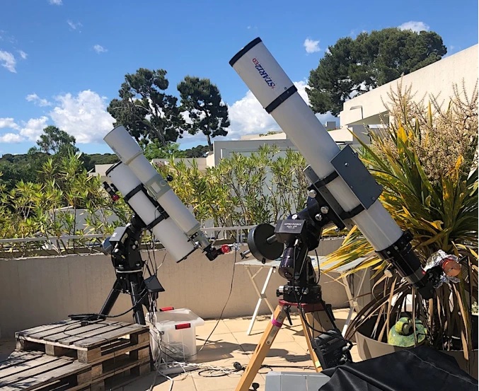
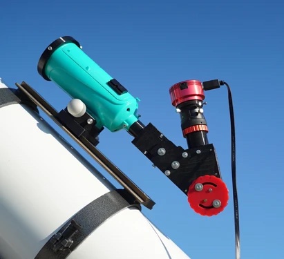
The following views show a number of combinations that are perfect for Sol'Ex:
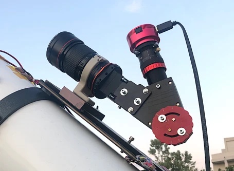
With a photographic telephoto lens with a focal length of only 200 mm.
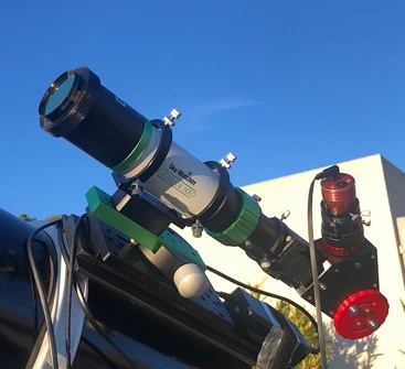
With a small EVOGUIDE SkyWatcher refractor D=50 mm, F=232 mm, which is used more as a finderscope.
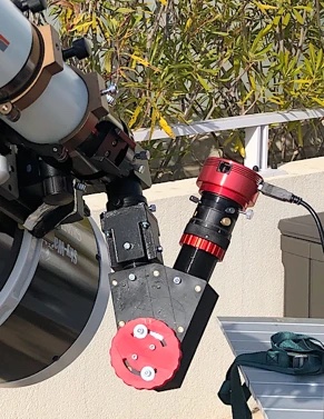
With a TS refractor with a diameter of 65 mm and a focal length of 420 mm.
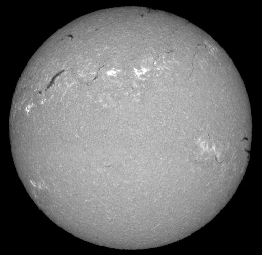
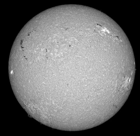
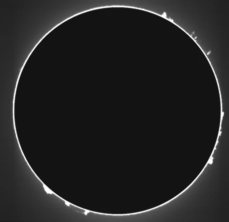
The following two images, taken with Sol'Ex, show the appearance of the solar disk in the H-alpha line for the two extreme configurations in this list:
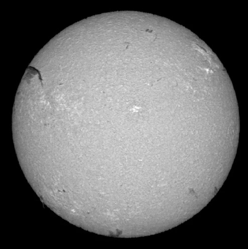
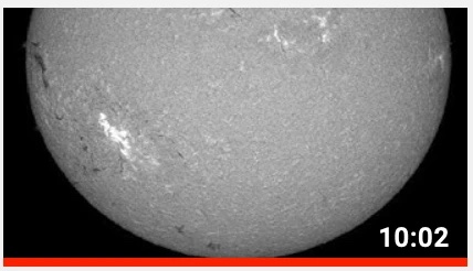
The image was taken with a Canon telephoto lens with a 200 mm focal length and an aperture of f/5.6. Despite the modest size of the instrument, this document reveals numerous details in the solar atmosphere (there was no visible white-light activity on the solar surface at the same time). This lightweight and affordable configuration is ideal for getting started and continuing to enjoy photography.
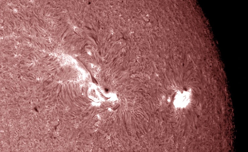
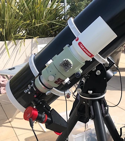
The image was taken with an FS128 refractor with a 1040 mm focal length. The setup is considerably heavier, but reveals fine details when the degree of atmospheric turbulence allows.
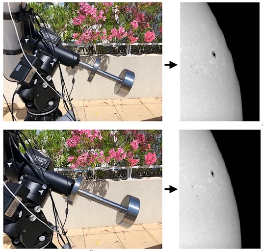
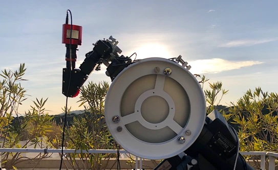
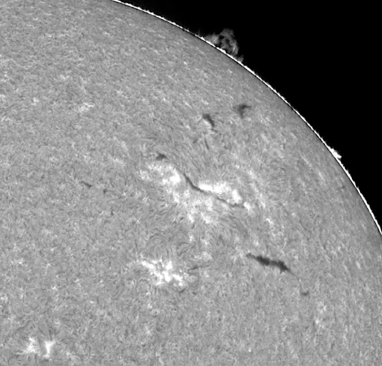
There is, however, an exception to the use of telescopes when they are small. The following example shows the use of Sol'Ex in conjunction with an Acuter Maksutov "educational" telescope with a 60 mm diameter and a focal length of 750 mm. For safe use (do not melt the plastic parts of this small telescope), it is necessary to attach an attenuation filter to the front of the tube – see the discussion on neutral density filters below. This configuration proves to be remarkable in several respects: (1) the purchase price for this type of optical tube is very low (100 euros), (2) the quality is really good, as the focal ratio is quite large (f/12.5) and the workmanship is very accurate, (3) the entire set (telescope and Sol'Ex with camera) weighs no more than 1 kg, (4) it is by no means a gimmick or a toy, but rather an "all-plastic" solution, very consistent with Sol'Ex and impressive for the performance achieved, while there is hardly anything cheaper for observing the Sun at home, in a school, etc.
Below is an image of the Sun taken on November 26, 2021, in the H-alpha line using a ¤100 optical tube (MaksyGO Acuter). A neutral density filter (ND4) on the front of the tube is mandatory and completes the set (see Part 5).
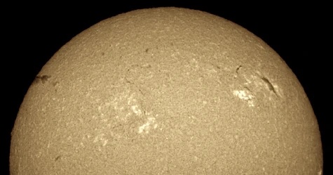
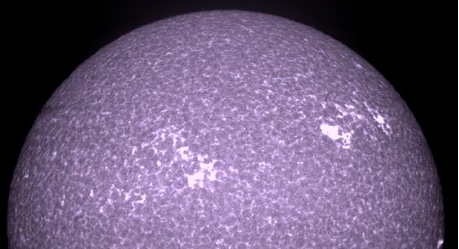
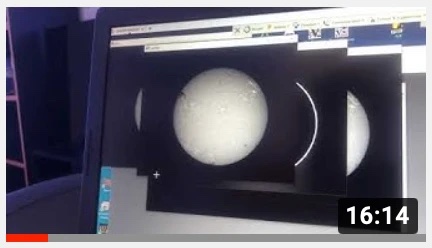
Due to the relatively long focal length (750 mm), it is not possible to image the entire disk with Sol-Ex in a single scan. The images above, corresponding to this single scan, were acquired with the ACUTER telescope on December 3, 2021, in the red hydrogen line at the top and the K line of Ca II at the bottom. Of course, it is always possible to create a mosaic of the northern and southern hemispheres to construct a complete disk.
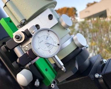
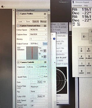
The quality of the focusing system is crucial for obtaining sharp images of the Sun. It must be free of play, translated, and reproducible (e.g., a good Crayford). Sometimes it is necessary to position the entrance slit of the Sol-Ex to within +/-0.010 mm, if not better. Adding a measuring device, such as a mechanic's micrometric caliper, proves useful. This element is attached to the telescope body, and the measurement is taken via a probe relative to the movable part that supports the Sol'Ex. There are many inexpensive models, both mechanical and digital (Christian prefers the mechanical ones with pointers, as they are easier to read in any position).
To assess whether the image of the sun is correctly focused on the Sol-Ex slit at the time the "scans" are captured, you have at least three criteria at your disposal:
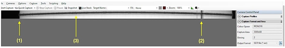
- The sharp edges at the tip of the leaf blade projected onto the slit. This is a "beach edge" (bright) test in optics jargon.
A jagged H-alpha line structure that changes rapidly as you pass the disc across the slit. This structure reflects the fluctuations in gas velocity in the chromosphere, which Sol Ex can detect very well (Doppler-Fizeau effect). The more chiseled the edges of the stripe, the better the sharpness, as this is a sign that you are seeing fine details.
If a spot is present on the disc and you have centered it on the slit, the black line it forms along the entire scattering axis will be more contrasty, the better the image is focused.
This procedure is explained in detail in a video, which you can watch by clicking on the following image:
capture-d-ecran-2021-08-31-a-23.35.24-434.webp
Note that the image is always captured with the camera oriented so that the deflection axis of the grating is vertical, and the spectral lines are therefore horizontal. This arrangement significantly optimizes the readout frequency of the CMOS sensors.
The question arises as to how Sol Ex should be oriented relative to the telescope to perform either a right ascension or declination scan. There are different schools of thought, but my opinion is to "scan" in right ascension without a doubt. This is more natural (and this is what you do when you perform a scan by turning off the telescope's drive motor). Often, the mechanical quality of the mount and drive is better with right ascension relative to the declination axis. Furthermore, if you are only capturing fractions of the solar disk in one pass because the focal length of the telescope is long, it makes astrophysical sense to work along an axis close to the equatorial plane of the solar disk, since the equatorial belt is often the most detailed.
Part 2: The Camera
Aside from the telescope (or telephoto lens), the most important financial investment for using Sol'Ex is purchasing the acquisition camera, if you don't already have one. The camera topic is discussed in Part 4 of the "Setup" section.
A small-pixel CMOS camera is generally preferable, such as the ASI178MM (pixel size 2.4 microns, ideal) or the ASI290MM/Mini (pixel size 2.9 microns). If you have a ZWO ASI174MM (or an equivalent camera from QHY), don't worry, you can use it; You'll get beautiful images of the sun without spending a cent, despite a pixel size of 5.86 micrometers, especially considering that models with small pixels often use 2x2 binning (software).
Color cameras, on the other hand, are not recommended except for educational purposes (showing the spectrum in color always makes a good impression!).
You'll need software to read the camera. You can find free programs like SharpCap or FireCapture, which can generate SER files (a sequence of individual images) at high speed. You'll need to tell the application to capture the data at 16 bits (not 8 bits). Familiarize yourself with the software when you first collect solar data.
For the camera to operate at high frame rates—often more than 100 frames per second are required—you'll need a computer with a USB3 interface. This is not only mandatory, but also standard today! In addition, the connection between the camera and the computer should be short and direct, rather than running through a hub, which usually doesn't provide the required playback frequency. Another important point is the windowing of the image to the useful area surrounding the line used for the solar image (cropping). It is important that the camera is aligned so that the spectral lines in the images are horizontal so that they can be read at the sensor's maximum speed, taking the sensor's internal architecture into account. In this case, the cropping area is much wider than it is tall. The width typically encompasses the entire width of the slit image. For an ASI178MM camera, for example, the window is 3088 pixels in the X direction and 140 pixels in the Y direction, corresponding to a crop of 3088x140.
During normal operation, during solar scanning, the camera's gain should not exceed 200 (20 dB in the ZWO reference system in the evening). Above this, noise becomes clearly visible. A gain of 100 is perfect, a lower gain even better. The gain is adjusted with the exposure time - see the next section.
Part 3: The Mount
As is well known, the principle of observation is to allow the image of the Sun to pass in front of the slit while taking regular, high-frequency images to scan the solar disk accurately and with good regularity. The images thus acquired are saved in a single SER file.
An equatorial mount is essential for this process to ensure orthogonality between the scanning direction and the long axis of the slit. In other words, the image of the disk through a telescope or binocular must move at a right angle to the long axis of the Sol-Ex slit. It is strongly recommended to maintain this perpendicularity without exceeding an error of 1 degree. If the angular error is 2°, you will be able to take and process images of the Sun, but some errors in the images may become problematic for certain applications. This means you need to properly align Sol Ex with the telescope and its attachment to the mount (see the following videos). Make marks when attaching and detaching Sol Ex to the imaging instrument.
The scan should be performed along the right ascension axis (not the declination axis), (1) for astrophysical analysis purposes (Doppler measurements, see below), (2) because the scrolling is often smoother with right ascension, and (3) because it is more logical and natural.
The speed at which the image moves from the disk across the slit has a significant impact on the quality of the resulting images and ease of use. A "natural" scroll at sidereal speed (15°/hour) corresponds to the drive motor being stopped during straight upward movement. This is certainly possible, but scanning the entire solar disk from east to west (or vice versa) takes more than 2 minutes. This impairs interactivity, and while the average motion is by definition very smooth, the turbulence of the images caused by atmospheric turbulence is clearly noticeable over such a long period. If you have a mount that allows catch-up speeds of 8x, 16x, etc., the sidereal speed, the scan will be much faster, and you're more likely to fall into a "hole" where the turbulence subsides. The scan is then called "forced." Here, the camera must be able to capture images at a high frame rate (several hundred frames per second) to obtain a nearly circular solar disk without requiring very significant post-processing. For more information on this point, see the "Processing" section of this website.
To obtain a nearly round disk immediately, a good coupling must be found between the chosen constraint speed (4x, 8x, 16x, etc.) and the exposure time for each frame comprising the scan, the camera pixel size, and the telescope focal length.
Then, the exposure time t required to obtain a round disk is given by the formula:
t = (8.79 . p) / (F . V . cos(delta))
where V is the assumed multiple of the sidereal speed (V = 4, 8, 16, etc.);
where t is the exposure time in seconds;
where p is the camera pixel size (after binning) in micrometers;
where F is the telescope focal length in millimeters;
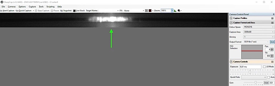
where delta is the declination of the Sun at the time of observation.Let's take an example. We use a refractor with a focal length of 420 mm (F = 420), and Star'Ex is equipped with an ASI178MM camera operating with 2x2 binning, corresponding to a pixel size of 2 x 2.4 micrometers = 4.8 micrometers (p = 4.8). We decide to scan the solar disk at 16 times the sidereal velocity (V = 16). At the time of observation, the Sun's equatorial declination was 23.42° (delta = 23.42) (for a quick calculation, you can set delta = 0°). After the calculation, we find:
t = (8.79 . p) / (F . V . cos(delta)) = (8.79 . 4.8) / (420 . 16 . cos(23.42)) = 0.00684 seconds.
This is 6.84 ms. This is the exposure time you need to specify in your image acquisition program to generate a SER file from which the image of the sun will be calculated. This exposure time corresponds to a frame rate of 1/0.00684 = 146 frames per second. You must ensure that the acquisition software (SharpCap, FireCapture, etc.) is capable of reading the camera's video stream at this frame rate. If you have set the acquisition window as described in the previous section, you should not encounter any problems (the image should circumscribe the spectral line of interest and nothing more). At the same time, after setting the exposure time, you should also adjust the camera's gain to prevent the continuum adjacent to the spectral line from becoming saturated (usually).
It's not certain that your speed of movement V will exactly match the displayed value, or that the sun's declination isn't taken into account. Therefore, you'll need to check the exact exposure time against the calculated value to obtain a round disk.
Demonstrate the above formula. E is the size of the detector pixel in arcseconds, projected onto the sky (the spectrograph's spatial axis; see also the formula for the size Vy in the "Theory" section of the website):
E = (206 p / F) x 80 / 125 (using the units used previously and 80/125 being the ratio of the focal lengths of the collimator and objective).
The angular displacement of the Sun in arcseconds during a time t (in seconds) in the direction of the compass in which it is located is given by the classical formula (synodic rotation of the Earth, i.e., 360° in 24 hours):
E' = 15 . V . t . cos(delta)
For the solar disk to be round, E = E', which, by approximating the corresponding equations, yields the equation we used to determine the exposure time.
Caution: At high scanning speeds, some mounts are subject to vibrations (resonator phenomenon), which have a dramatic effect on the quality of the solar images. The result depends on the direction of tracking (east or west) and the balance of the mount. Check the smoothness of the Sun's limb (outside of turbulence) to ensure everything is OK. Consider selecting the best scanning direction (east to west or vice versa).
Above, the mount is balanced to produce clearly visible oscillations on the solar limbus when the disk is scanned at 4x sidereal speed with an FS128 refractor. Below, the mount is balanced differently, and the oscillations have completely disappeared. The image of the Sun shown is the result of processing a Sol-Ex acquisition outside any lines, resulting in a classic image of the Sun's photosphere, here with a spot.
Part 4: Sol'Ex's Thermal Shield
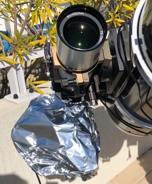
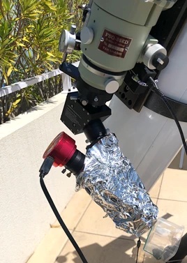
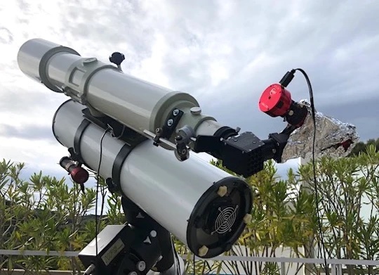
When using Sol'Ex as shown in the image above, you expose the black housing to the sun, and the temperature of the housing rises very quickly. This causes thermoelastic deformation of the plastic Sol'Ex is made of, with the visible effect of the spectrum shifting more or less randomly in the plane of the sensor. It's impossible to work this way, as conditions may have changed between the start and end of a scan.
It is therefore imperative (really "mandatory") to keep Sol'Ex at a temperature close to ambient, which means placing a shield between the sun and Sol'Ex. I use a really simple technique that compromises aesthetics, is effective, doesn't add weight, and doesn't provide any additional wind protection: Wrap Sol'Ex in kitchen aluminum foil (use the double-layer variety to reduce tearing problems). This is what the image above shows... guaranteed effective!
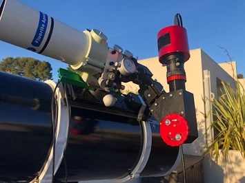
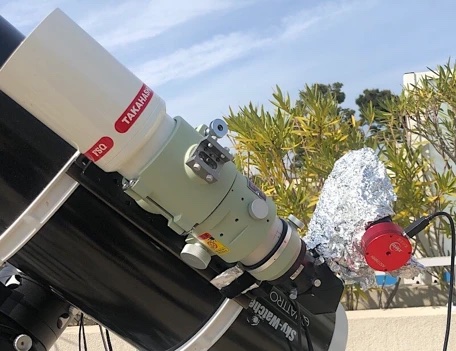
Below: Protection by aluminum foil against temperature rise while Sol'Ex is mounted in the focal point of a Takahashi FSQ85ED
Part 5: The Attenuation of Sunlight
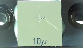
The recording instrument (telescope or camera lens) concentrates a high amount of energy onto a small area at the focal point. The temperature at this point is high unless an element is used to absorb or reflect this energy. This is precisely where the Sol'Ex entrance slit is positioned. It is a very thin strip of glass coated with chromium (inclined 30° to the optical axis), a material that both reflects and absorbs. The slit pattern is drawn on it (a 4.5 mm long and 10 micrometer wide, transparent line). The glass is glued to another piece of aluminum that serves as the support material. These two pieces can carry the energy contained in the focused image of the sun, but the differential expansion of glass and metal can lead to mechanical stress and breakage. This can be seen in the adjacent image: a slit that has broken due to prolonged exposure to intense, focused solar radiation without any attenuation.
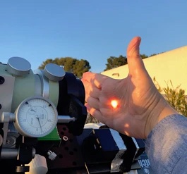
Therefore, it's important to attenuate the solar flux to a certain extent to ensure the instrument's functionality. To check whether the attenuation is sufficient, place your palm at the focal point of your telescope. If you can hold it there for at least 15 to 20 seconds, you can assume there won't be any problems using Sol'Ex.
The simplest way to reduce sunlight intensity is to place a neutral density filter at the entrance of the telescope or camera lens. Filters are available from HOYA or B+W in various densities at quite reasonable prices, up to a diameter of 82 mm. The correct density values for us are between 0.6 and 1.2, depending on the instrument used. For example, for a telephoto lens with a focal length of 400 mm and an aperture of 5.6 with a focal length doubler (f/11.2 - see videos below), we use a particularly bright filter with a density of 0.6. For a 200 mm lens with an aperture of 5.6, the value is ND = 1.2.
HOYA offers a wider density range than B+W. The HOYA filters are also cheaper and don't exhibit color fringing, which is not the case with the B+W filters tested, which can be annoying for certain types of work. In summary, the HOYA PROND filter series is the right source.
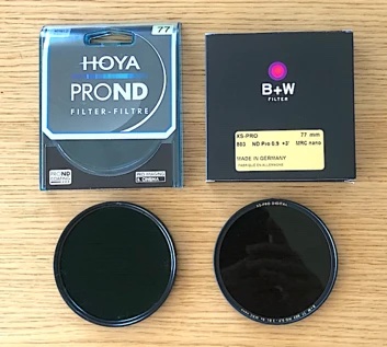
Many different diameters are available, corresponding to the standards of photographic lenses: D=62 mm, 67 mm, 77 mm, 82 mm... It is up to you to choose the diameter that best suits the diameter of your telescope, but allow a surcharge of 2 to 5 mm.
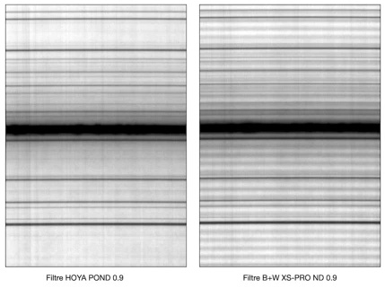
On the right, you can see the fringing pattern observed with the B+W neutral density filters. This pattern is absent from the HOYA PROND12 filter, which is recommended for most situations, while it is only slightly visible with the ND8 or ND4 filter.
The good news is that the photographic filters are effective across a wide range of wavelengths, not only in the visible range but also in the infrared range. If in doubt, you can screw an infrared-cut filter (IR-cut) onto the 31.75 mm tube connecting the Sol Ex to the telescope—this isn't necessary with the specified filters. For your information: solar energy below 400 nm accounts for 3% of the total energy, between 400 and 700 nm it accounts for 42% of the total energy, between 700 and 1100 nm it accounts for 34% of the total energy, between 1100 and 1700 nm it accounts for 15% of the total energy, and beyond that, into the infrared range, it accounts for 6%. The exact ratio depends on atmospheric transmission, but you can see that the infrared component, which is invisible to the naked eye, is not negligible.
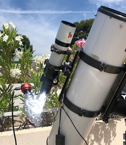
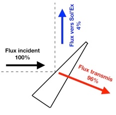
Another way to filter the intense solar flux is to use a Hershel helioscope, a well-known accessory for solar observers. This looks like the angled deflector of a telescope. The principle is simple: the solar flux collected by the telescope strikes a bare (untreated) glass plate, usually tilted at a 45° angle, slightly in front of the focal point. A bare glass surface naturally reflects about 5% of the incident luminous flux and transmits the rest, i.e., 95% (the internal absorption of the glass is practically zero). The resulting attenuation eliminates the risk of the material being damaged by the helioscope (although it is forbidden to observe with the naked eye without further filtering). The second side of the slide forms an angle with the first to prevent ghosting.
The following image shows some Herschel wedges available on the market for 31.75 mm casting:
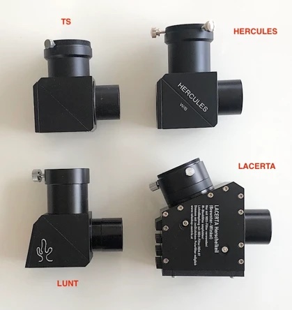
After evaluation, the use of the TS model in the specific context of Sol'Ex applications proves disappointing, as a particularly absorbent polarizing treatment on the glass slide significantly reduces the overall brightness, resulting in insufficient light in some cases, which is a problem when observing the Sun (the TS helioscope behaves as if it had a density of approximately 1.8). The LUNT, HERCULE, or BAADER models, which use an untreated slide, are perfectly suitable. The LACERTA model uses an untreated slide at a specific angle of incidence, the so-called Brewster angle, which maximizes the linear polarization induced by the slide. This property, combined with the fact that Sol'Ex itself polarizes the light, more than 75% in the red (due to the diffraction grating), maximizes the overall transmission, which proves to be an advantage. Despite its bulky appearance and high optical pressure, which means it won't fit all glasses (make sure you can focus), the LACERTA is the ideal helioscope for use with Sol'Ex. How to operate a helioscope is explained in a video linked below.
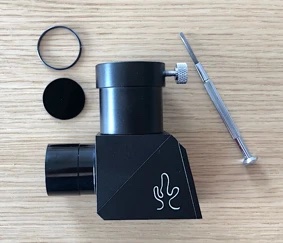
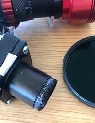
A neutral density filter may be installed in the helioscope when it is delivered (see right). If this is the case, this filter must be removed, as must any polarizing filters provided by the manufacturer.
The following photos show how the Hershel helioscope should be aligned with respect to the mount (the most common case of right ascension scanning) and how the Sol Ex should be aligned with respect to the helioscope. The way these elements are mounted is not intuitive, but it is crucial to note them. The origin of this arrangement lies in the shared polarization of the helioscope and Sol'Ex to maximize the optical flux transmitted through the system.
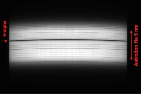
Here's a tip about filters to improve image quality. Note that using a filter is completely optional, as Sol Ex produces good images on its own. The idea is to reduce the amount of background noise when observing prominences at the solar limbus. If you have such an accessory, add a 5- to 10-nanometer-wide H-alpha bandpass filter, which is typically used to facilitate the observation of gaseous nebulae in the sky, in front of the slit. Adding a prefilter reduces instrumental scattering. Of course, this idea only applies to the H-alpha line.
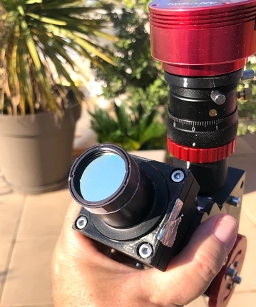
Above, the installation of a narrowband H-alpha filter at the entrance of Sol Ex. Below, the appearance of the spectrum in the region of the H-alpha line when a bandpass filter is used: only the light from the immediate vicinity of the line enters the spectrograph, thus reducing internal scattering.
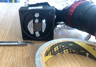
One final note to conclude this section: The glass slit is mounted on a black anodized aluminum part. This metal piece absorbs more heat than the glass part. To ensure that the temperature doesn't rise when observing with a large instrument, you can make this absorbing part of the slit mount reflective by applying strips of aluminum tape to the corresponding parts, as shown in the photo to the right (but be sure not to stick anything to the glass part!).
Part 6: Observing with a 200mm telephoto lens and a density filter.
To get to grips with Sol'Ex, don't hesitate to use a smaller instrument; it's the best way to learn. In the following videos, Christian shows you, for example, how to use a simple 200mm focal length camera lens, which allows you to obtain interesting and demonstrative images of the Sun's surface in the red hydrogen line (H-alpha), as well as many other lines.
The videos in this part show the most important things you need to know to use Sol'Ex.
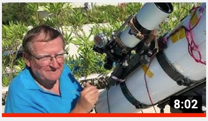
In the first video (click on the image), Christian explains step by step how to attach the lens to Sol'Ex, how to use a density filter, how to focus the disk, and more:

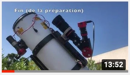
The next video shows how to prepare Sol Ex for actual observation by covering the topics of sun alignment, focusing the spectrum, focusing the solar image (see also part 1 of this page), and aligning the instrument:
The last video in this part shows how to perform a scan, how to use the SharpCap acquisition software, and how to use the INTI software for fast scan processing and solar disk display:
Part 7: Observing with an 800mm telephoto lens and a density filter.
This part describes how to use a lens with a longer, still photographic, focal length. It's a 400mm telephoto lens combined with a focal length doubler. The images produced with this system are significantly more detailed (but they don't show the entire disk in one pass):
capture-d-ecran-2021-09-01-a-01.54.57-428.webp
Part 8: Observing with a Herschel Helioscope
The following video explains how to use a Herschel Helioscope in conjunction with a 65 mm diameter, 420 mm focal length refractor. It particularly addresses the important issue of aligning Sol Ex with the helioscope:
Part 9: How to Observe Sunspots
While Sol'Ex is very good at producing images of the Sun using light from narrow spectral lines, you should not forget that you can also very effectively produce images of the photosphere and thus, for example, sunspots using light from the spectral continuum. The following video (click on the image) shows how to do this, particularly using the INTI software:
Part 10: The Importance of Binning and the Focal Length of the Telescope.
Binning combines neighboring pixels into a single pixel. For example, 2x2 binning combines the signal from pixels forming a square with two pixel sides. With CMOS sensors, binning is achieved through a simple arithmetic summation, which is less efficient than with CCD sensors, which perform analog summation. Software such as SharpCap offers this option for binning during acquisition.
For us, binning serves three purposes: First, it reduces noise somewhat during observation. Second, it significantly reduces file size. At a constant sampling rate, an SER file acquired with 1x1 binning is eight times larger than one acquired with 2x2 binning, which is a significant difference.
Conversely, with 1x1 binning, the spectrum and the solar disk (along the spatial axis) are sampled more finely than with 2x2 binning. The image is therefore potentially more resolved. For example, the following two images of prominences were acquired in continuity with 2x2 binning and 1x1 binning (subsequently scaled):
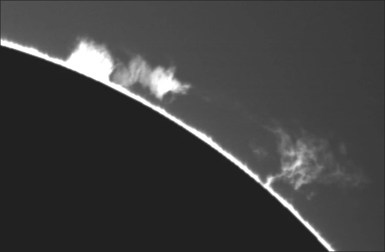
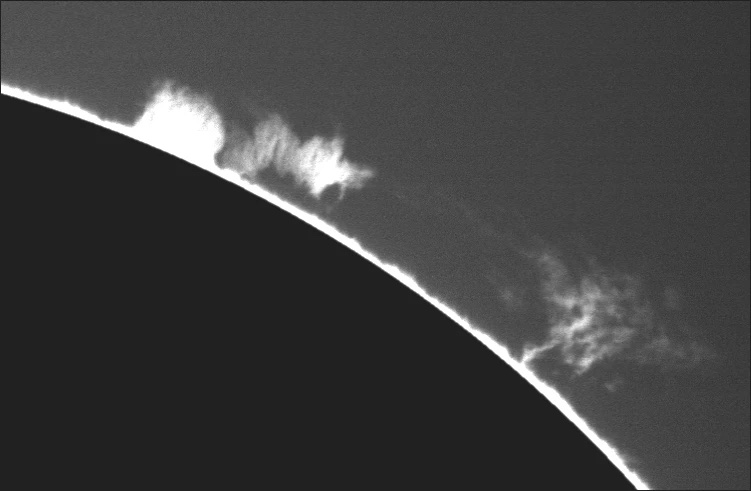
A closer look at these images reveals a resolution gain from using 1x1 binning. The Sol'Ex theory is thus confirmed. However, this gain must be weighed against the size of the images, which reduces flexibility of use and interactivity.
Caution: 2x2 binning reduces spectral resolution compared to 1x1 binning. If you need to make precise measurements in the spectrum or work with very fine lines, 1x1 binning is necessary.
The other way to increase image resolution is to use a larger acquisition device, which extends the focal length. Of course, this is much more expensive than simply choosing the binning factor, but performance increases much faster, as demonstrated in the following video:
This Product was added to our catalogue on 19/11/2022.
")

Die Box kann unter tpl_modified/boxes/box_miscellaneous.html verändert werden. Die Sprachvariablen befinden sich in der Datei tpl_modified/lang/german/lang_german.custom.