- Kundengruppe: Gast
-


- Registrieren
- Anmelden
- Mein Konto
- Startseite
- Details
- Mehr Bilder
Produktbeschreibung
Problemstellung:
Bei einer Celestron Evolution Montierung (>3 Jahre) passierte gar nichts mehr, wenn man sie einschaltete, weder die Handbox/Controller ging an, noch erfolgte ein Aufladen der Batterien (erkennbar an der rot aufleuchtenden Diode an der Seite) oder eine sonstige Reaktion.
Der Kunde beschrieb, dass sich nach dem letzten Einschalten der Montierung, diese sich mehrmals um die eigene Achse drehte und dabei wohl auch den Ladekabelstecker abrissen und dabei auch zerbrach.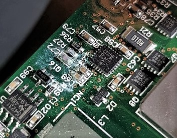
Tests der Handbox an einer anderen Celestron Montierung bei uns zeigte, dass diese fehlerfrei funktionierte. Auch der Anschluss eines neuen Ladekabels führten zu keiner Reaktion der Montierung.
Bei und nach der Öffnung der Montierung fielen Korrosionsspuren an Schrauben, Anschlüssen und auf der Platine auf. Und auch der leicht "elektronische-anmutende" Schmauchgeruch wiesen zunehmend darauf auf hin, dass es zu einem Kurzschluss auf der Platine gekommen sein musste.
Lösung:
Da die Montierung einen 4-stelligen Anschaffungspreis besitzt und Celestron Einzelteile (wie die Platine) anbietet, lohnte sich ein Austausch der Platine. Die bestellte Platine kam mit einem sogenannten Retropfit-Paket daher.
Denn die Platine der mehrere Jahre alten Montierung besaß die Version Evo Rev F (steht für Evolution Revision Version F), während die neue Platine vom Typ Evo Rev J war.
Damit waren nicht mehr alle Stecker kompartibel und doch etwas Bastelarbeit gefragt, um die Platine neu anschließen zu können.
Im Retrofit enthalten sind: neue Platine (hier Typ J), ein neues internes Power Kabel sowie Stecker und Kabelklemmen.
Da wir auch den Verdacht hatten, dass das interne Powerkabel auch in Mitleidenschaft gezogen wurde, passte das gut.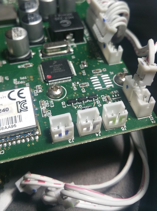
Schritt 1:
Ausbau der Platine.
Dazu zieht man vorsichtig alle mit der Platine verbundenen Stecker ab und löst die 4 Metallschrauben.
Tipp: Wer hier nach dem Einbau der neuen Platine vermeiden möchte sich stundenlang in Schaltpläne zu vertiefen, macht ein Photo vor dem Platinenausbau und markiert die gleichaussehenden Anschlussstecker farbig, damit man danach sofort weiß, wo welches Kabel hin muss! Dies beugt ggf. auch unnötige Fehlersuche im Nachgang vor ;-)
Schritt 2:
Tipp: Neue Platine für die folgenden Schritte noch n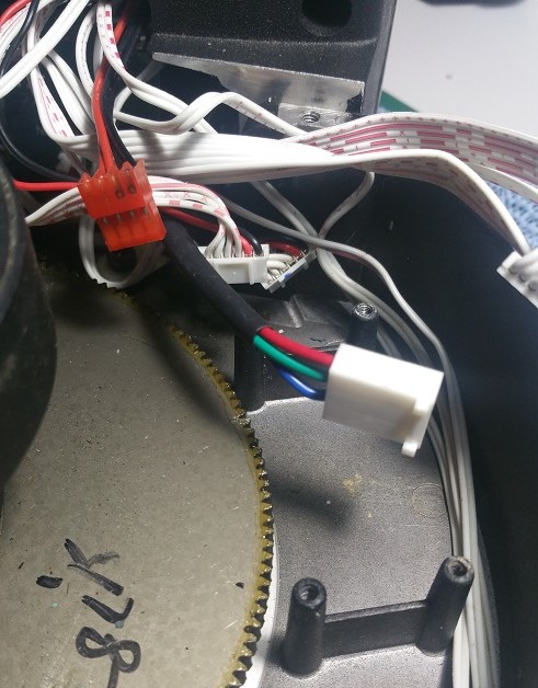 icht einbauen, das sorgt für mehr Platz zum Hantieren und beugt mögliche Kontaktschäden an der neuen Platine vor.
Nun baut man das alte interene Stromkabel vom Ladekabelstecker ab. Am einfachsten geht das, wenn man zuvor auf der Gegenseite die Konsole an den beiden Schrauben links und rechts gelöst hat.
Nun baut man das neue Kabel ein und kann die Konsole wieder anschrauben.
Schritt 3:
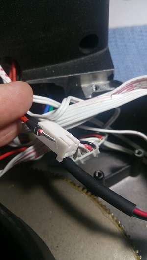
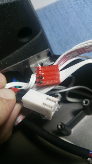
Jetzt muss der alte Anschlussstecker von der Batterie umgebaut werden. Denn der neue Anschluss kommt mit 2 Adern, statt wie bisher 4 daher. Der Stecker ist leicht an den 2 ankommenden roten und 2 schwarzen Kabeln erkennbar. Mutig schneidet man alle 4 Kabel unmittelbar nach dem Stecker ab. Nun löst man die Isolierung vom Kabel (ca. für 5mm) und verdreht die zwei freien roten Kabel miteinander und klemmt sie (in den im Paket enthaltenen) in die Kabelklemme (siehe Photo). So verfährt man auch mit den zwei schwarzen Kabeln. Sicherheitshalber haben wir die 2 verdrehten Kabel noch mit Isolierband zusammengebunden.
Anschließend steckt man die nun von 4 auf 2 reduzierten Kabelanschlüsse in den Anschlussstecker.
ACHTUNG: Die flache Seite zeigt zum Steckerfenster!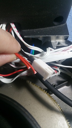
Schritt 4:
Nun kann die neue Platine eingebaut werden. Hierzu bitte Kontakt mit dem Fett auf dem großen Zahnrad vermeiden. Am besten ist sowieso die Platine nur an den freien Ecken anzufassen.
Hat man alles richtige gemacht, passen alle Stecker und die farbigen Markierungen helfen die alten Stecker wieder an den richtigen Platz zu bringen.
Bevor man zuschraubt, führen wir immer einen Funktionstest (freies Drehen, als auch ein 2 Star Alignment) durch.
Mit neuem Ladekabel und upgedatetem Handcontroller funktioniert nun die Montierung wieder einwandfrei.
Tipp: Wie Sie den NexStar+ Controller updaten können, finden Sie: >>hier
Beim und Nach dem Zusammenbau haben wir die Montierung noch gereinigt. Nun schaut es fast aus wie neu ;-)
Wem das zu bastelig ist, der darf uns gern zwecks Austausch und Prüfung (gegen einen kleinen Unkostenbeitrag) und/oder Updates kontaktieren. ;-)
-


Diesen Artikel haben wir am 11.11.2018 in unseren Katalog aufgenommen.
Profitieren Sie von unseren Erfahrungen als Teleskop-Spezialisten:
denn sehen heißt verstehen
in besonderen Fällen auch Vor-Ort-Service im Raum München

Infos / Tricks / Tipps »
Mehr auf Ihrer privaten Seite »

Die Box kann unter tpl_modified/boxes/box_miscellaneous.html verändert werden. Die Sprachvariablen befinden sich in der Datei tpl_modified/lang/german/lang_german.custom.